Improving Reliability in Claus Temperature Measurement
Lowering Costs & Improving Reliability in Claus Temperature Measurement
By Steve Croom, VP
Delta Controls Corp.
Description: Published Paper; Presented at the Sulfer 2001 International Conference, Marrakech, Morocco
Monitoring temperatures of the hot face of the refractory in Claus Thermal Reactors is done mainly for two reasons:
- To protect the Claus Thermal Reactor so as to maximize its service life and minimize costly downtime
- Reduce maintenance expenses
There are essentially two types of devices suitable for monitoring the temperature of Claus Thermal Reactor refractory. These are the Thermocouple and the Infrared Radiation Pyrometer. Although both have proven to be effective over many years of Claus Reactor service, both technologies are encumbered with drawbacks and operational problems.
Thermocouples
Thermocouples are the standard industrial temperature measurement method that has proven to generally be the most cost effective, accurate and reliable technology for over 100 years. Thermocouples, while normally requiring no periodic maintenance, have gained a reputation in Claus Thermal Reactor service as being unreliable. This is considered to be an unfair assessment by some designers. Nevertheless, “thermocouple technology”, per se, suffers with this reputation, which has primarily arisen from the attempted use of modified standard industrial thermocouple designs, which are unsuitable for this service.
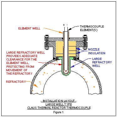
Thermocouple design advancements have overcome the problems associated with corrosion and high temperature found in Thermal Reactors. The thermocouple still has a lingering poor reliability reputation with some users. There are still some failures, which are normally the result of improper installation. Such failures result from shifting refractory, damaging the protective well. Such damage exposes the metallic thermocouple element to corrosion and eventually causes it to fail. Choosing a large refractory well thermocouple specifically designed for Claus Thermal Reactors, installing it properly and operating it within the published guidelines will provide accurate temperature measurement for years with no maintenance. (Fig. 1)
For a period of time following the breakage of a thermocouple protective well, the operator of the reactor may not be aware that thermocouple corrosion has begun. Thermocouple failure can be a slow process. As the corrosion progresses, the T/C output signal will gradually drop relative to the actual temperature. This “low” error may allow the reactor to be operated at undetected higher and higher temperatures.
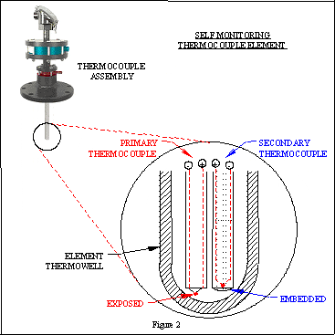
This potential error problem has been solved by a thermocouple design enhancement that provides a “self-monitoring” feature that warns of a failing T/C element. This new design incorporates two separate independent operating thermocouples, a primary and secondary. (Fig. 2). The primary one is installed in the conventional position inside the element well and is constantly flushed with N2 or clean, dry instrument air and provides the fast response needed for operations. The secondary T/C is installed adjacent to the primary T/C, but it is embedded in a solid ceramic-blend sealant material. It is not exposed to the flush gas or to the reactor gases if the thermowell becomes damaged. The secondary T/C output signal is the “reference” signal and because it is embedded in solid ceramic material, is slower to respond than the primary T/C element and therefore it is not suitable for use as the primary operating measurement.
In the event of a mechanical failure due to improper installation, shifting refractory or thermal shock severe enough to break the element protective well, the primary thermocouple element would be exposed to the reactor gases. Gradually, the now exposed primary element would become corroded and its output signal would slowly begin to drop relative to the actual reactor temperature. On the other hand, the secondary T/C, which is encased in a solid ceramic sealant material, would be shielded and therefore become contaminated at a far slower rate than the “exposed” primary thermocouple. This makes the secondary thermocouple relatively immune to the corrosive gases and permits it to provide an accurate output signal for a considerable period of time after contamination of the primary element has begun. Therefore, in the event of a thermowell failure, the two output signals would show an increasing deviation from each other. This deviation in output signals provides a warning that corrosion has begun on the primary thermocouple element and that it is necessary to plan to begin to use alternate temperature monitoring methods, such as other thermocouples, infrared or even analyzers.
This new thermocouple design warns of inaccuracy and prevents the operator from relying on a failing thermocouple’s gradually diminishing output signal. This prevents false low readings, which can allow undetected high temperature to damage the refractory.
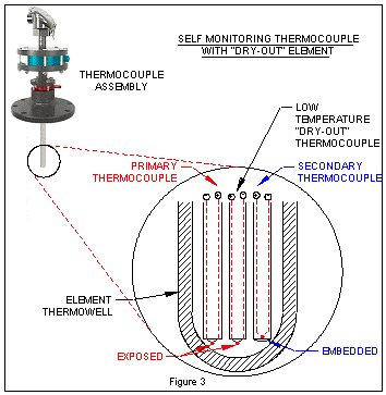
Another new thermocouple development is the addition of a third thermocouple element, which is used as a “refractory dry out” temperature sensor. (Fig. 3) This very accurate thermocouple element, usually a “T” type, is used to measure the critical low temperatures (usually 658C to 3008C) required to properly cure the newly installed refractory material. This additional thermocouple element provides an easy means to accurately monitor this temperatures without having to install additional thermocouples or to change wiring as the reactor is brought up to operating temperature. As the “dry out” is completed and the reactor operating temperatures are reached, this thermocouple element burns up without damaging the other elements. The advantage of this third thermocouple is that it permits accurate control of the refractory dry out cycle and reduces costs during the startup period. With the new thermocouple, all three, the primary, secondary and the dry out T/C’s are all permanently wired through the assembly’s conduit head, eliminating the need to install temporary wiring for “dry out”. This simplifies the installation and avoids the need to later remove the exposed wiring under operating conditions.
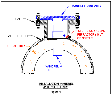
Improper installation practices have been identified as the primary reason that the otherwise suitable thermocouple designs sometimes suffer a relatively short life. Research and development efforts have developed methods to improve the quality of thermocouple installations. The main problem with thermocouple installations has been the creation of the “bore-hole” through the refractory below the mounting nozzle. For many years, an installation “mandrel” (Fig 4) has been the only tool available for creating the proper bore size, centering the hole in the nozzle and maintaining the alignment of the hole relative to the mounting flange. The mandrel is bolted onto the mounting flange prior to installing the refractory; the refractory is then installed in the normal manner around the protruding tube that extends down into the reactor. As soon as the refractory sets, the mandrel is removed, leaving a proper bore hole for the thermocouple installation
A recent modification to the mandrel design incorporates an adjustable “Stop-Disc” that is used to keep refractory castable and mortar from entering the base of the nozzle and upsetting the critical dimensions that are required for successful thermocouple installation. If castable refractory material is permitted to enter the base of the nozzle, the top surface of the refractory will extend up beyond the vessel shell. If this condition is not corrected, the refractory well will not be installed in the proper position, causing interference with the element well and probable failure of the element well during installation or startup
In recent years, refractory installers have preferred to drill the bore hole through the refractory instead of mounting the mandrel, which requires that the refractory brick be cut and fitted around the mandrel pipe.
But, it has been found that creating a “drilled” hole that is on-center, straight, uniform and of the proper bore size, is very difficult to achieve. Boring an incorrect hole through the refractory is very likely to cause the thermocouple assembly to become broken by shifting refractory, which will result in early failure. Also, once an improper hole is cut in the refractory, it is very difficult, expensive and time consuming to correct it.
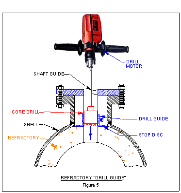
To assure proper drilling of the refractory, a new “Drill-Guide” is now available (Fig. 5). The “drill-guide” is mounted to the nozzle flange. The refractory core drill is inserted down inside the guide pipe, which extends down into the nozzle to within approximately 25-mm of the refractory. The guide pipe is slightly larger than the drill size, which is typically 2.25 inches (approximately 60-mm). At the top, a drill shaft centering guide is adjusted to help keep the drill bit aligned so that a straight perpendicular bore hole, located in the exact center of the nozzle is created. Proper positioning of the hole insures that shifting refractory will not place high stress loads on the protective well. When the installation is to be made in new refractory, the “stop-disc” is used to keep the castable refractory or mortar from entering the nozzle.
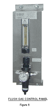
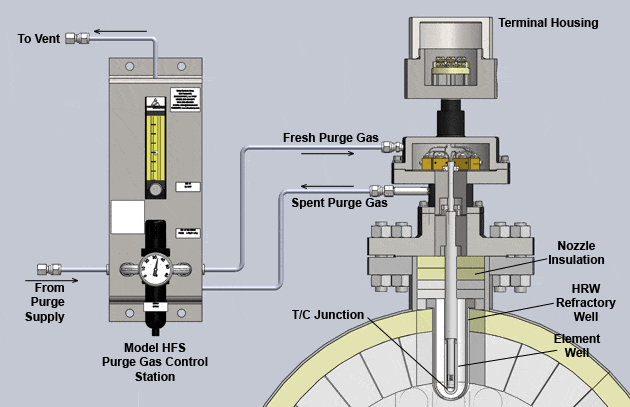
After proper installation, the only operating requirement is that N2 or clean dry instrument air flush gas pressure and flow is maintained through the thermocouple. Although the element protective well is designed to be “gas-tight”, certain ions and elements may migrate directly through the wall of the thermowell at high temperatures and if not flushed out, will +accumulate and eventually corrode the thermocouple elements. To assure that the necessary flush gas hardware is provided and installed in the proper manner, a pre-piped flush gas panel is now available (Fig. 6). This panel not only provides the necessary components to measure and control the pressure and flow of the flush gas, but also assures that the proper piping and connections are in place. Without the proper flush gas installation and operation, contaminants will enter through the wall of the thermowell and eventually corrode the thermocouple element causing inaccuracy and ultimate failure.
The use of Claus Thermal Reactor “large-refractory well” type thermocouples with self monitoring primary and secondary thermocouple elements, properly installed and operated, will provide years of accurate maintenance free temperature measurement.
Infared
Infrared has become a very popular means to monitor Claus Thermal Reactor temperature. The main reason is that it does not come in contact with the hot corrosive reactor gases. Nor is it installed in a manner whereby it may be damaged by shifting refractory. On the other hand, Infrared technology suffers from certain drawbacks. The primary ones are that it is expensive, is not inherently accurate in the Claus environment and can require hazardous, costly and frequent maintenance. Also, the IR cannot measure the low temperatures required during the refractory”dry out” and curing phase.
The primary difference between the thermocouple and the IR device is that the IR device does not inherently measure temperature. Instead, it measures the intensity of radiated energy, and as such, it infers the temperature measurement. What this means is that the IR device must be “told” what the actual temperature is and then the IR will measure the deviations from that selected temperature as long as the operating conditions do not change.
The main maintenance and error problem of the IR is that the sight path into the reactor can become occluded or blocked, either from condensed sulfur vapors collecting on the viewing window or by the vessel nozzle becoming filled with particulate matter over time. Such things as refractory emissivity and the mix of the reactor gases also effect accuracy of the IR device. Another problem is variable absorption of the radiation by the reactor gases. The commonly used lead sulfide IR sensors, associated electronics and mechanical choppers cannot withstand the high ambient temperatures of the vessel and mounting nozzle, requiring that the instrument, lens assembly and the nozzle be cooled with water and a high volume of purge gas. This lead sulfide type sensor also “ages” causing it’s output signal to drift over time, resulting in varying degrees of inaccuracy in the readings.
To control the problems associated with obscured sight paths, it is necessary to periodically clean the nozzles and the lens assemblies. To perform this task, the nozzle block valve is closed, the lens assembly removed and a seal-gland equipped cleaning rod assembly is mounted on the nozzle. The rod is used to physically push the material out of the nozzle and into the reactor while it is operating. Then the rod assembly is removed and a similarly mounted rod-type thermocouple is inserted into the reactor to obtain the actual temperature at the base of the nozzle. The lens assembly is cleaned and then reassembled. The IR unit is then manually adjusted to provide an output signal that matches the temperature measured by the inserted thermocouple. This is accomplished by adjusting an “emissivity” control, which corrects for instrument aging changes, changes in the surface of the refractory or changes in the composition of the gases. Note that this “inserted” thermocouple can only be inserted a distance just beyond the base of the nozzle near the refractory hot face; it cannot be placed against the other side of the vessel from which the IR energy is being radiated. Therefore, there is no way to verify an accurate temperature of the face of the refractory on the opposite side of the reactor (unless, of course, a thermocouple is installed in that location).
This type of maintenance requires the utmost in safety precautions and is expensive. Corrosive gases attack the stainless steel jacket of the inserted thermocouples, which are sacrificed with each insertion. The “inserted” thermocouple recalibration effort only resets the accuracy of the IR device at one specific temperature; IR suppliers typically recommend that the instruments be periodically removed and returned to the factory for full range and linearity re-calibrations. These expensive full range calibrations are performed in a black body furnace, which provides a perfect emissivity environment and corrects the signal over the entire measurement range. However, when the IR instrument is again reinstalled in the reactor, it must again be manually reset to a temperature measured by a thermocouple inserted into the nozzle. This is because the factory is unable to calibrate the unit under the exact same conditions that exist in that particular location in that particular Thermal Reactor using the same exact gas composition.
A new IR technique has been developed to minimize or perhaps completely eliminate these drawbacks. This new technique employs four distinct features:
- Drift free sensor using advance silicon technology
- Remote mounting sensor and electronics
- Unique “hot nozzle” lens assembly
- Empirical radiation filtering techniques to minimize absorption errors
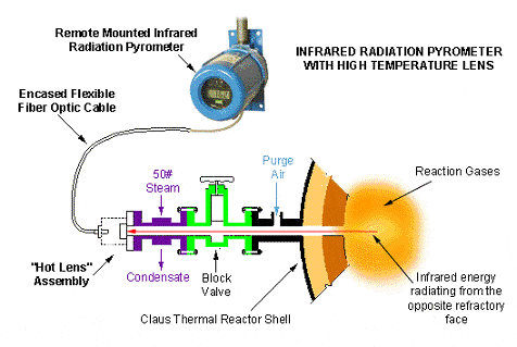
Periodic recalibration is unnecessary with the use of the silicon technology sensor. This sensor is superior to the lead sulfide type technology in the Claus application because it does not exhibit the same tendency to drift, age and become inaccurate over time. However, the silicon type sensor cannot withstand the high temperatures encountered at the mounting flange of the reactor nozzle. Typically, temperatures at the nozzle may reach up to 1758C. It is for this reason that the sensor / electronics unit is mounted separately from the reactor nozzle and connected to the viewing lens via a special fiber optic cable. This installation permits the sensor and electronics to operate in a suitable environment and eliminates the need to cool the reactor nozzle or the instrument.
Cooling of the nozzle encourages the sulfur species to condense onto the viewing window, which blocks the sight path of the IR sensor. If the viewing window were maintained at a higher temperature, sulfur vapors would remain in a gaseous state and not precipitate onto the viewing lens or inside the nozzle.
Remotely mounting the IR sensor and electronics not only protects the electronics from the excessive heat, but also permits the lens assembly to operate at even higher temperatures than those normally occurring in the nozzle. Adding heat to the nozzle solves the problem of obscured sight paths. This higher temperature insures that sulfur cannot precipitate onto the viewing window surface or plug the nozzle.
To maintain the proper amount of heat, a new design IR nozzle adapter incorporating a steam jacketed window assembly, is maintained at approximately 150°C, well above the temperature where sulfur will precipitate onto surfaces. Maintaining this high temperature causes the sulfur to remain in the gaseous state and not collect on the viewing window or precipitate into liquids or solids that will accumulate in the nozzle. A purge flow is maintained at the base of the lens assembly to discourage particulate matter from collecting in the nozzle. This purge flow is also heated.
A steam jacketed fiber optic cable adapter is mounted to the nozzle. Heat is maintained by routing 50# steam through the nozzle jacket. The fiber optic cable and lens assembly, which routes the IR infrared radiation to the remotely mounted sensor, is capable of withstanding 2008C.
Field tests to date have shown that this combination of the remote-mounted silicon sensor with the steam jacketed nozzle window prevents buildup of sulfur on the window assembly. Other purged nozzles on the same reactor did accumulate a buildup of sulfur that would have partially occluded the IR’s view and cause a reading error. The silicon sensors combined with the use of fiber optic cable have exhibited no temperature deviations compared with adjacent thermocouples. No maintenance or recalibration has been required.
This change to the silicon “non-drift” electronics technology, coupled with the high temperature window design solves most of the maintenance problems and improves long term accuracy.
It is recommended that both Infrared and Thermocouples be employed in measuring Claus Thermal Reactor refractory temperature. The reason is that upsets or conditions that may cause failure of a thermocouple would likely not have any harmful effect on an Infrared unit. Similarly, the conditions that may cause the Infrared to become inaccurate will likely have no effect on the thermocouple. Thermocouples are inherently accurate and do not rely on manual “calibrations” or “adjustments” to maintain correct readings. The combination of thermocouple and infrared radiation sensing provides the utmost in reliability and accuracy. The operator has a good reading and something to which it may be compared.
It is well recognized that the measurement of the temperature of the hot face of the Claus Reactor refractory is one of the most severe and demanding applications in industry. By addressing each of the unique characteristics of this difficult measurement, accurate and reliable monitoring can be done at a relatively low cost.
Summary
To achieve the lowest overall cost, highest reliability temperature measurement capabilities
- Use both thermocouples and Infrared devices for utmost accuracy and dependability.
Infrared
- To minimize the need to clean nozzles and windows, use steam jacketed purged IR lens assemblies
- Select remote mounted properly filtered advanced technology IR transmitters that reduce the need for periodic recalibration
- Select instruments with multiple band radiation filtering
Thermocouples
- Select “self-monitoring” large refractory well type Claus Thermal Reactor Thermocouples with “self-monitoring” capability and “dry out” temperature measurement capability
- Use all available installation tools to insure proper refractory dimensions for thermocouple installation. This will eliminate mechanical breakage problems due to improper installation.
- Install the recommended flush gas control components in the proper piping sequence. Periodically observe that the proper flush gas flow and pressure are maintained.

