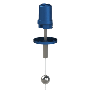
Float Switch, Top Inserted, Two Point
The Delta Controls Model 710 Float Switch offers two configurations, A and D, for variable liquid output switching. Model 710A provides output switching at two points based on a varying liquid level. The 710 is commonly used with a preliminary warning which announces that ‘shutdown’ may soon occur and remedial action should be taken at once.
The unit is located on top of the vessel with the primary element extending down into the vessel. The float rides on the surface of the liquid and is carried up and down as the liquid level varies. The attractor is coupled to the float by the float rod and also moves up and down as the level varies. The attractor is located inside of the barrier tube and is in contact with the process fluid.
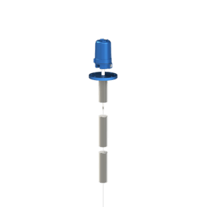
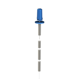
The switching stations are located on the outside of the tube and are isolated from the process fluid. Each station contains a magnet which is magnetically attracted to magnetic materials such as the attractor. The attractor is lifted into the magnetic field of the bottom switch station. The magnet is pulled in against the barrier tube, an output switch is connected to the magnet and is actuated. Additional increases in the liquid level lift the attractor into the magnetic field of the top switch station and its output switch also actuates. Falling liquid level sequentially pulls the attractor out of the field of the switch station magnetic fields and each output switch deactuates. Separation between the two output switch actuation points is two inches to three inches, depending on the actual specific gravity (SPG) of the liquid.
The 710 should be mounted vertically on top of the vessel. The guide tube/float rod must be long enough so that the float centerline extends down approximately two inches below the point where switch action is desired. A baffle or stilling well is required if the fluid is agitated or has surface turbulence; otherwise the switching action may be erratic. The switching points are fixed by the length of the float rod/guide tube. The process connection should be large enough to admit the float into the vessel. If not, then the float must be unscrewed from the float rod and installed from inside the vessel after the body/attractor assembly has been mounted on top of the vessel.
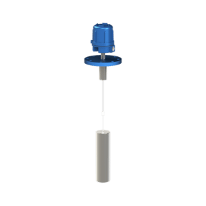
The Model 710D Differential Option has a single switch station and is equipped with a differential device. The station activates at a high level and remains activated unit the liquid level falls to a lower elevation. The additional amount that it must fall, before the station deactivates, is called the Differential. This amount is adjustable from about one inch to two and one half inches depending upon the specific gravity (spg) of the liquid. The 710D is commonly used where a considerable amount of surface agitation or splashing is expected to occur. This design results in a more stable and reliable alarm action, particularly as the level approaches the switching point. It can also serve as a pump control in large tanks.
Features
- Variable liquid output switching
- Both high and low level alarms
- Attractor located inside barrier tube
- Switching stations located outside tube
- Vertical mounted on top of vessel
- Two fixed switching points
Specifications
- Wetted Materials: 316 Stainless Steel, carbon steel
- Insertion (Below Process Connection): ≤ 10 ft
- Switch Action: 2 alarm points and/or differential
- Sensing Element: 316 Stainless Steel
- Specific Gravity: 0.43 to 2.40
- Temperature Range:-150 °F to +750 °F (-101 °C to +399 °C)
- Pressure : -15 psig to +730 psig (-1.0 bar to +50 bar)
- Threaded Process Connection:1.0 in to 3.0 in MPT
- Flange Rating:≤ 300 lb ANSI flanges, Grayloc® hub, DIN or JIS equivalents
Certifications & Approvals
- Third Party Listed by CSA NRTL/C (USA and Canada) Class I, Division 1, Groups B, C and D; Class II, Division 1, Groups E, F and G; Class III, Division 1 Class I, Zone 1, Ex d IIB+H2 Class I, Zone 1, AEx d IIB+H2
Required Ordering Information
- Detailed model number
- Tag or nameplate detail (if required)
- Documentation/testing tiers (if required, refer to Additional Resources in the product catalog)
- Process fluid or material name*
- Process fluid or material specific gravity
- Maximum process temperature
- Maximum process pressure
- Upper and lower materials required for interface service